Decoding the Connection and Phase Displacement Symbols for Three-Phase Transformers
Published:
In the world of electrical engineering, understanding the connection and phase displacement symbols for three-phase transformers is crucial. These symbols, defined by the IEC 60076-1-2011 standard, provide a concise way to describe the configuration of a transformer.

Unraveling the Transformer Connection Symbols
The connection of a set of phase windings in a three-phase transformer, or of windings of the same voltage in single-phase transformers associated in a three-phase bank, can be represented using capital letters Y, D, or Z. These letters stand for star, delta, or zigzag connections respectively for the high-voltage (HV) winding. For the intermediate and low-voltage (LV) windings, the same connections are represented by small letters y, d, or z.
When the neutral point of a star-connected or zigzag-connected winding is brought out, the indication changes to YN (yn) or ZN (zn) respectively.
In the case of open windings in a three-phase transformer, where the windings are not connected together in the transformer but have both ends of each phase winding brought out to terminals, the indication is III (HV) for high-voltage windings, or iii for intermediate or low-voltage windings.
For an auto-connected pair of windings, the symbol of the lower voltage winding is replaced by ‘auto’, or ‘a’, for example, ‘YNauto’ or ‘YNa’ or ‘YNa0’, ‘ZNa11’.
The symbols for the different windings of a transformer are noted in descending order of rated voltage. The winding connection letter for any intermediate and low-voltage winding is immediately followed by its phase displacement ‘clock number’.
Special Cases in Transformer Connections
There are special cases in transformer connections that are worth noting. The existence of a stabilizing winding, which is a delta-connected winding not terminated for external three-phase loading, is indicated, after the symbols of loadable windings, with the symbol ‘+d’.
If a transformer is specified with its winding connection changeable (series-parallel or Y-D), both connections will be noted, coupled with the corresponding rated voltages. For example, a transformer with a changeable connection could be indicated as YN(YN)d11 for a 220(110)/10,5 kV transformer or YNy0(d11) for a 110/11(6,35) kV transformer.
Practical Examples of Transformer Connections
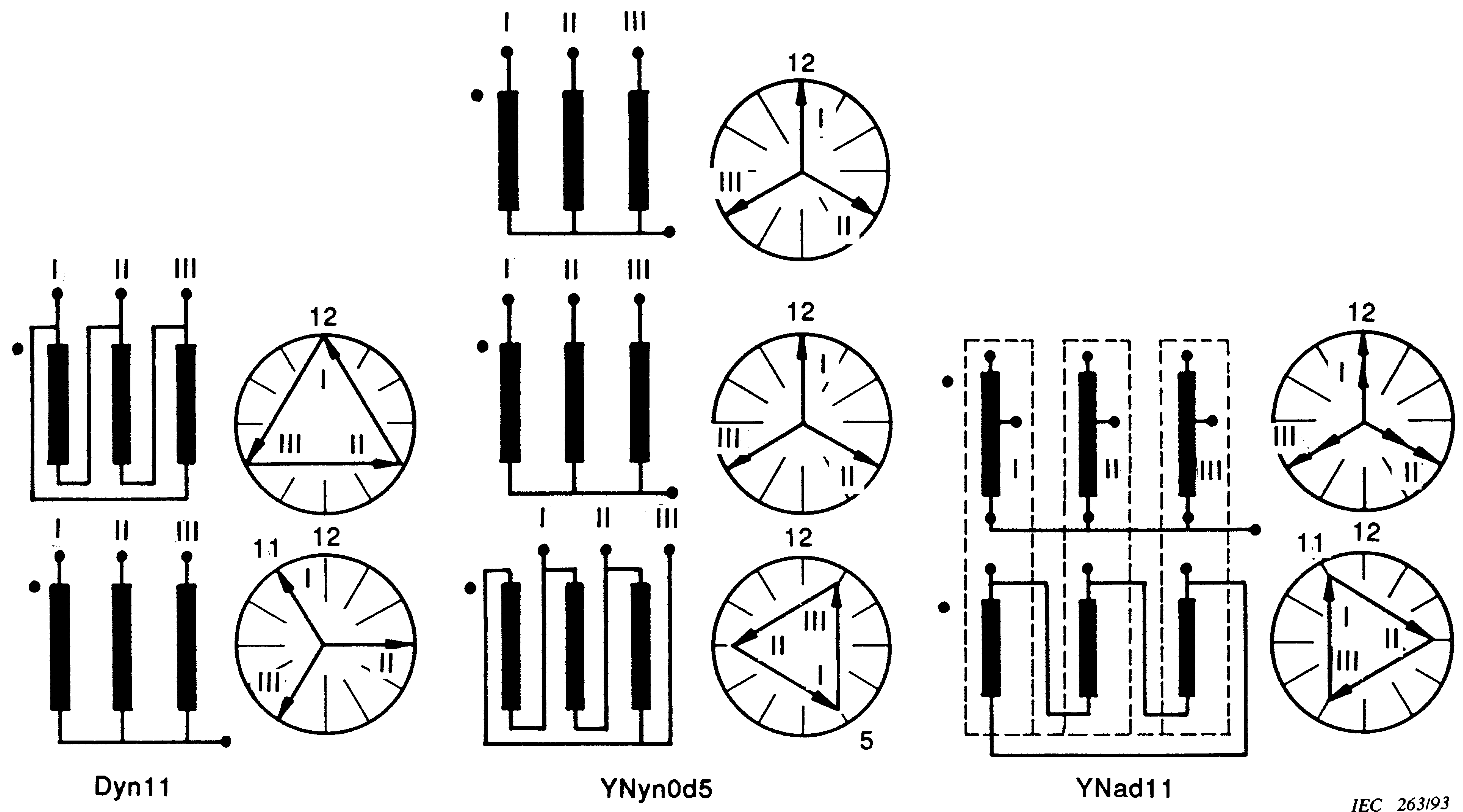
To better understand these symbols, let’s look at a few practical examples:
Dyn11: This symbol represents a distribution transformer with a high-voltage winding for 20 kV, delta-connected. The low-voltage winding is 400 V star-connected with neutral brought out. The LV winding lags the HV by 330°.
YNyn0d5: This symbol represents a three-winding transformer: 123 kV star with neutral brought out. 36 kV star with neutral brought out, in phase with the HV winding but not auto-connected. 7,2 kV delta, lagging by 150°.
YNautod11 or YNad11: This symbol represents a group of three single-phase auto-transformers 3 130 3 400 kV with 22 kV tertiary windings. The auto-connected windings are connected in star, while the tertiary windings are connected in delta. The delta winding phasors lag the high-voltage winding phasors by 330°.
In the case of a three-phase auto-transformer with the same connection, internally, the symbol would be the same. If the delta winding is not taken out to three line terminals but only provided as a stabilizing winding, the symbol would indicate this by a plus sign. No phase displacement notation would then apply for the stabilizing winding.
Conclusion
Understanding these symbols is key to interpreting the configuration of a transformer. Whether you’re an electrical engineer or a student studying electrical systems, this knowledge is fundamental to your work and studies. Remember, full information about the transformer should be given on the rating plate as per the IEC 60076-1-2011 standard.

